CMM-Manager provides tools for airfoils and blade inspection on a CMM using CAD-driven path planning to measure cross-sections, twist, chord length, thickness, and surface profiles. CMM-Manager on your CMM provides GD&T capabilities, certified algorithms, and automated inspection workflow, providing an optimal solution for aerospace applications where regulatory traceability and repeatability are essential.
Why Use CMM-Manager for airfoil inspection?
- Accuracy & Traceability – CMMs provide micron-level accuracy and PTB/NIST-certified algorithm traceability, which is crucial in aerospace.
- CAD-Driven GD&T – CMM-Manager directly evaluates tolerances against CAD using ASME Y14.5/ISO GPS standards.
- Repeatability – Automated programs ensure consistency across batches and operators.
- Flexibility – Works on different CMM hardware using the same software environment and programs.
- Regulatory Compliance – Aerospace OEMs often require inspection against CAD and GD&T, which CMM software supports.
Reporting and airfoil specific capabilities
Typical Parameters Inspected
- Chord Length – distance between leading and trailing edge along defined sections.
- Twist Angle – rotation of sections along the span.
- Camber Line & Maximum Camber – curvature of the airfoil section.
- Leading/Trailing Edge Radii – critical for aerodynamic efficiency and structural performance.
- Airfoil Thickness Distribution – measured at multiple cross-sections.
- Profile of Surface / Line – GD&T evaluation against CAD along section cuts or full surface.
- Platform Geometry – dimensions, true position, and flatness of blade root platform.
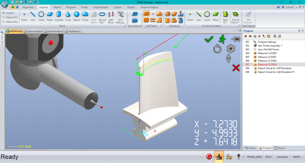
CAD-Driven Inspection Path
- Using the CAD model, a probe path is generated along critical sections of the blade (chordwise and spanwise cross-sections).
- CMM-Manager can use curve and surface probing (single points or scanning paths) to gather high-density data across leading edge, trailing edge, suction side, and pressure side.
- Automatic collision-avoidance and fixture “furniture” 3D CAD (imported into software) ensures smooth path execution.
Measurement Strategy
- Combination of discrete point probing and continuous scanning with probes like Renishaw SP25 or REVO for full surface coverage.
- Automatic collision-avoidance and fixture “furniture” 3D CAD (imported into software) ensures smooth path execution.
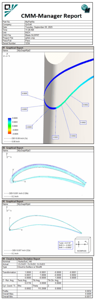
Report data and visualization
- Graphical reports highlight systematic deviations – e.g., twist error along an airfoil
- Visual reports are easier to understand for non-metrology staff (design engineers, machinists, suppliers, or customers).
- Create text and graphical reports that can be saved (PDF, HTML, MS Excel, TXT) or printed.